
If you have ever looked at a set of plans and understood the rooms but not the heights, layers, or inside of the walls, you were missing the section view. When people ask what is a cross-section drawing, they are usually trying to understand how architects, contractors, and permit reviewers see the building beyond the floor plan.
A cross-section drawing is a vertical cut-through view of a building or space. It shows what you would see if you sliced through the structure and looked straight at the cut. That makes it one of the clearest ways to understand floor-to-floor heights, roof slopes, stair relationships, wall assemblies, ceiling changes, windows, doors, and how different parts of a building line up from bottom to top. For homeowners, designers, and property managers in California, sections are especially helpful when planning remodels, additions, ADUs, tenant improvements, and permit packages based on existing conditions.
What is a cross-section drawing?
At the simplest level, a cross-section drawing is a scaled drawing that represents a building as if a vertical plane cut through it. The cut exposes elements that are normally hidden, such as framing depth, ceiling cavities, slab edges, roof structure, stair profiles, and the relationship between finished floor, top plate, ceiling, and roof line.
Unlike perspective images, sections are not about visual realism. They are technical drawings used to communicate dimensions, construction relationships, and design intent. A section may cut through an entire building, one room, a stair, a wall, or a specific assembly that needs closer explanation.
In a typical drawing set, cross-sections work together with plans, elevations, and detail drawings. If you are new to plan sets, it helps to first understand what as-built drawings are and how each drawing type contributes different information.
- Plans show horizontal layout.
- Elevations show exterior or interior faces straight on.
- Sections show the inside of the building vertically.
- Details zoom in on specific connections or assemblies.
What a cross-section drawing shows
A good section answers questions that are hard or impossible to resolve on a floor plan alone. It clarifies how spaces stack, how tall they are, and what exists above, below, or behind finished surfaces.
Common information shown in a cross-section drawing includes:
- Floor-to-floor heights and ceiling heights
- Roof shape, slope, and overhang relationships
- Wall thicknesses and major assembly layers
- Stair rise, run, landings, and headroom
- Window and door head heights and sill heights
- Foundation, slab, crawlspace, or basement conditions
- Soffits, beams, dropped ceilings, and structural depth
- Site grade relative to the structure in building sections
In existing buildings, these drawings can reveal why a renovation is more complex than it first appears. A section may show that a ceiling is lower than expected, that roof framing interferes with a new skylight, or that a bathroom floor steps up over existing plumbing. This is one reason sections are often produced from measured field conditions, not assumptions.
How a cross-section drawing is created
To produce an accurate section, someone first needs reliable base information about the building. FastAsBuilt starts with on-site laser measurement, then senior drafters turn those field measurements into permit-ready CAD files delivered in PDF and DWG format. Depending on the project, the section may be drawn from measured dimensions, visible conditions, photographs, and related plan views.
For straightforward homes and smaller spaces, the section may be based on a 2D as-built package. For more complex buildings, vaulted ceilings, split levels, or renovation planning where vertical relationships matter, a 3D workflow can be especially useful because the model helps coordinate floor plans, elevations, and sections together. If you are comparing deliverables, it also helps to review what is included in as-built drawings.
Most sections are created through a process like this:
- Measure the site and existing structure
- Draft the floor plan and major reference geometry
- Select the cut line where the section will best explain the building
- Project visible and cut elements into the section view
- Add dimensions, levels, notes, and material cues as needed
- Coordinate the section with plans and elevations so they match
The key point is accuracy. A section is only as useful as the underlying measurements and drafting discipline behind it.
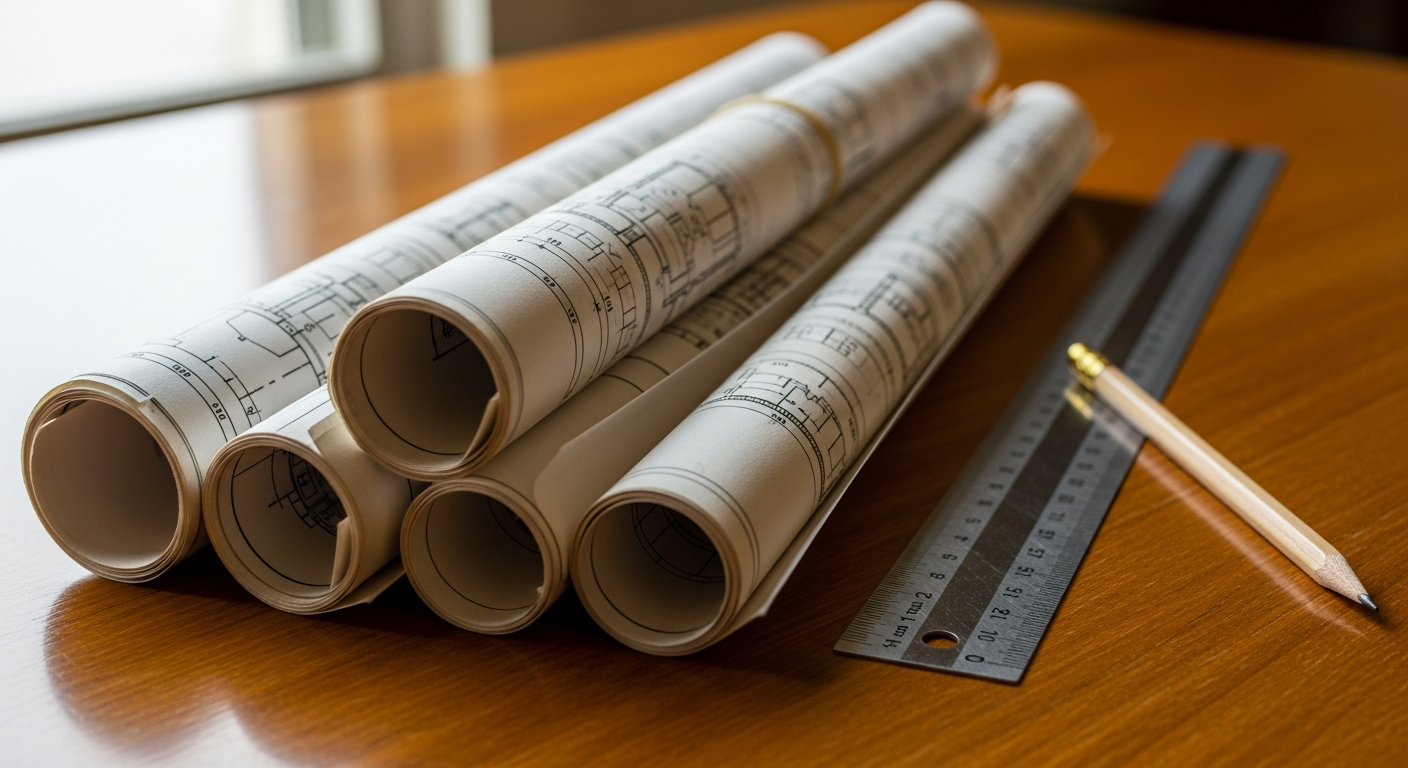
Cross-section drawing vs floor plan
One of the most common comparisons is cross-section drawing vs floor plan. Both are essential, but they answer different questions. A floor plan is a horizontal slice, usually cut a few feet above the floor, showing the arrangement of walls, rooms, doors, and circulation. A cross-section drawing is a vertical slice showing height, depth, and internal relationships from side to side or front to back.
If you imagine a house as a loaf of bread, a floor plan is like slicing it parallel to the countertop, while a section is like cutting straight down through the loaf. Each cut reveals different information.
- Floor plan: best for room layout, wall locations, door swings, and overall circulation
- Cross-section: best for heights, roof form, stairs, ceiling changes, and structural relationships
- Elevation: best for exterior appearance or interior wall faces
On California remodels, this distinction matters. A floor plan may show where a new bathroom will go, but the section helps confirm whether there is enough ceiling height, how the new vent route may fit, or whether a roof slope limits usable space. If you want a foundational comparison to pair with this topic, see what an as-built floor plan is.
Cross-section drawing example
A simple cross-section drawing example is a cut through a one-story living room and kitchen. The section might show the slab below, finished floor above, wall framing at each side, a vaulted ceiling over the living room, standard ceiling height over the kitchen, roof rafters above, and a beam where the two ceiling conditions meet. Windows would appear in profile, and notes might identify head height, ceiling height, and roof pitch.
Another common example is a stair section. Instead of only showing the stair on plan, the section reveals each riser and tread, the landing depth, guard location, floor thicknesses, and the headroom above the stair. This is often the easiest way to spot conflicts early.
For a split-level home, the section can be even more important than the plan. It may show:
- How one level steps down from another
- The relationship between finished floor and exterior grade
- Whether a lower level is partially below grade
- How roof framing changes over different parts of the house
- Where ducts, beams, or soffits reduce ceiling height
This is why sections are so often included in permit and design conversations. They make vertical conditions obvious.
Need accurate as-built plans?
FastAsBuilt sends a local crew to laser-measure your property and delivers permit-ready 2D or 3D drawings, starting at $900.
See 2D & 3D pricingTypes of cross-sections you may see
Not every section serves the same purpose. In residential and light commercial drawing sets, several section types appear regularly.
Building section
A building section cuts through a large portion of the structure, sometimes from foundation to roof. It shows the big picture and helps explain the overall form of the building.
Wall section
A wall section focuses on one assembly or a small area. It may show siding, sheathing, framing, insulation, waterproofing, interior finish, and how the wall meets the floor or roof.
Detail section
A detail section zooms in further on a specific junction, such as a window head, parapet, stair edge, or roof-to-wall connection.
Site or grade section
Some projects need a section that shows how the building sits relative to sloping ground, retaining conditions, drainage, or adjacent exterior spaces.
These section types often appear alongside related drawing categories. For example, a section may work closely with an elevation drawing to explain both appearance and internal construction.
When cross-sections are needed on California projects
Not every small drawing package needs a full set of sections, but many California projects benefit from them, and some jurisdictions or design professionals will expect them. Sections are especially useful when permit reviewers need to understand the existing structure and the proposed work clearly.
They commonly help with:
- Kitchen and bathroom remodels with ceiling or structural changes
- Room additions and second-story additions
- ADUs and garage conversions
- SB 9 lot split or unit development planning
- Tenant improvements in commercial spaces
- Historic property renovations, including Mills Act properties
- Title 24 coordination where building form affects energy documentation
California rules and local review requirements can vary by city and county, so it is important to confirm exactly what your jurisdiction wants in the permit set. At a general level, sections help reviewers understand life-safety, height, and construction relationships, but they do not replace engineering where structural analysis is required. For existing multifamily properties dealing with balcony or exterior elevated element issues under laws such as SB 721 or SB 326, section-type drawings may also be useful for documenting existing conditions, though the required scope should always be confirmed with the appropriate inspector, design professional, or local authority.
For accessory dwelling units, small-lot changes, and other code-sensitive work, having measured existing conditions first usually reduces confusion later. If you are budgeting for that step, FastAsBuilt’s 2D As-Built Plans start at $900 for up to 1,500 square feet, then $0.50 per square foot, with one revision and typical 48–72 hour delivery. 3D As-Built Plans start at $1,500, then $1.00 per square foot, and include a 3D model plus 2D floor plans, elevations, and sections, with two revisions and typical 3–5 business day delivery. Custom commercial, ADU, SB 9, and tenant improvement projects are quoted individually.
Turnaround times are estimates and may vary based on project complexity and scheduling.

What makes a useful section drawing
A section should do more than exist in the set. It should answer real questions. The best section drawings are placed intentionally and drafted clearly so someone reading them can understand the building without guessing.
A useful section usually has:
- A logical cut line through the most informative part of the building
- Clear poche or lineweight to distinguish cut elements from items beyond
- Consistent scale and coordination with the floor plan
- Dimensions, levels, and notes where they matter most
- Readable openings, stairs, roofs, and structural elements
- Enough information to support design or permit review without clutter
If the section is based on existing conditions, the drawing should also reflect the limits of what was observed and measured. Hidden conditions inside walls or above ceilings are not always fully knowable without destructive investigation. Good drafting communicates what is confirmed, what is inferred, and what still requires field verification.
How to read a cross-section drawing
If you are not used to technical plans, sections can look dense at first. The easiest way to read one is to start from the floor plan. Find the section marker or cut line on the plan, then match it to the section number and sheet reference. Once you open the section view, read it from the ground or lowest level upward.
- Identify the finished floor lines
- Look for ceiling heights and level markers
- Find doors and windows shown in profile
- Trace roof slopes and structural depth
- Notice grade lines and exterior relationships
- Read the notes for materials, framing, or special conditions
It also helps to understand the graphic conventions used in construction drawings. If symbols, scales, and cut lines still feel unfamiliar, this guide to reading as-built drawings symbols, scales, and conventions gives helpful background.
As you compare drawings, remember that no single sheet tells the whole story. Sections make the most sense when read together with plans, elevations, and any detail callouts that expand on critical areas.
Common mistakes and misunderstandings
Many project delays start with a simple misunderstanding about what a section is supposed to communicate. The most common issue is assuming a floor plan already contains enough information. It often does not, especially when roofs, stairs, split levels, or structural changes are involved.
Other frequent mistakes include:
- Cutting the section in the wrong location, so the drawing misses the important conditions
- Failing to coordinate heights between plan, elevation, and section
- Showing too little information to support permit review
- Overloading the section with notes that belong in details instead
- Assuming hidden framing or MEP routing without verification
Another misunderstanding is thinking every section must show every material layer. That is not always true. The level of detail depends on the purpose. An existing conditions section for planning may be simpler than a construction wall section intended to explain a new assembly. The drawing should match the decision it is meant to support.
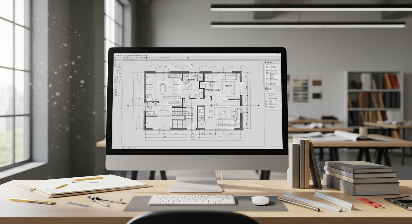
How cross-sections fit into as-built drawings
As-built documentation is about recording what is actually there. In many projects, sections are one of the most useful parts of that record because they help explain conditions that a plan alone can hide. When a property owner, architect, or contractor starts with measured as-builts, the team can make decisions based on real geometry rather than assumptions.
Cross-sections are especially valuable when the building has:
- Vaulted or irregular ceilings
- Complex roof framing
- Multiple levels or split floors
- Stairs, lofts, mezzanines, or conversions
- Existing beams, soffits, or bulkheads that affect new work
That is one reason many clients choose a package that includes coordinated section views from the start. If you are evaluating options, you can review as-built drawing costs in California and then place an order through our order page when you are ready.
Frequently asked questions
Is a cross-section drawing the same as an elevation?
No. An elevation shows the face of a building or wall as viewed straight on, without cutting through it. A cross-section drawing cuts through the building and shows internal vertical relationships, such as floor levels, ceiling heights, roof structure, and wall depth.
Do I need a cross-section drawing for a remodel?
Often, yes—especially if your remodel affects ceilings, roofs, stairs, windows, structural elements, or anything where height and internal relationships matter. Some small cosmetic projects may not need sections, but many California permit packages benefit from them. Always confirm requirements with your local jurisdiction and design professional.
What is a cross-section drawing example in a house?
A common example is a section cut through a living room and kitchen showing the slab, wall framing, ceiling heights, roof slope, beams, and window profiles. Another is a stair section showing risers, treads, landings, and headroom.
Can a section drawing show existing conditions only?
Yes. Sections are often used to document existing conditions as part of an as-built set. They can also be combined with proposed design information later. For existing buildings, the accuracy of the section depends on what was measured and what could be directly observed.
What is the difference between a cross-section drawing and a floor plan?
A floor plan is a horizontal cut showing room layout and wall locations. A cross-section drawing is a vertical cut showing heights, levels, assemblies, and internal building relationships. In short, a plan explains where things are across the space, and a section explains how they relate from bottom to top.
Start with accurate as-builts
Order field-measured 2D or 3D as-built drawings and let a local crew handle the measuring and drafting.
Get instant pricingBottom line
If you are asking what is a cross-section drawing, the short answer is that it is the drawing that reveals the building vertically. It shows the inside of the structure in a way a floor plan cannot, making it essential for understanding heights, roofs, stairs, assemblies, and existing conditions. For California homeowners, architects, contractors, and property managers, accurate measured sections can make remodel planning, permit review, and construction coordination far smoother—especially when they are built from on-site laser measurement and professionally drafted as part of a complete as-built package.