
If you want to know how to read as-built drawings, the good news is that the basics are learnable. Once you understand where to look first, how dimensions are organized, and what common floor plan symbols mean, the sheets become much easier to use. Whether you are planning a remodel, checking existing conditions before permit submittal, or reviewing a property for due diligence, as-built drawings are meant to show what is actually there.
That is the key difference. Design drawings show what someone intends to build. As-built drawings document the structure and layout as measured in the field. If you are new to the topic, it helps to start with what as-built drawings are and why they are used before getting into line weights, notation, and architectural drawing scale. This guide walks through the conventions you will see most often so you can read a plan set with more confidence.
Start with the purpose of the drawing set
Before reading any individual line or symbol, identify what the drawing set is trying to communicate. An as-built set is not just a picture of a building. It is a record of existing conditions at the time of measurement. That means the information is organized to help owners, architects, engineers, contractors, and permit reviewers understand the current layout and physical features of the property.
In practice, an as-built package may include some or all of the following:
- Floor plans showing rooms, walls, doors, windows, and built-in elements
- Exterior elevations showing building faces and vertical relationships
- Sections that cut through the building to show heights and assembly relationships
- Roof plans, reflected ceiling plans, or other specialty sheets when needed
- Notes that explain assumptions, field conditions, and items outside the scope
As you review the set, ask a simple question: what decision is this drawing supposed to support? If you are checking whether a proposed ADU will fit, the dimensions and wall locations matter most. If you are evaluating façade changes or window replacement, elevations and opening sizes may matter more. If you are coordinating mechanical, electrical, or plumbing work, you may need to confirm whether the set includes those systems; this is covered in whether as-built drawings include electrical and plumbing.
Read the title block and sheet information first
The fastest way to get oriented is to look at the title block. Many readers skip it and go straight to the plan, but the title block tells you how to interpret everything else on the page. It usually appears along the bottom or side of the sheet and includes the project name, property address, drawing title, sheet number, date, and revision information.
On a measured existing-conditions set, the title block may also help you understand who prepared the drawings and when. That matters because a property can change over time. A garage conversion, enclosed patio, tenant improvement, or removed wall may not appear if it happened after the field measurement date.
What to look for in the title block
- Sheet title: Confirms whether you are looking at a floor plan, elevation, section, roof plan, or detail.
- Sheet number: Helps you follow references between pages, such as A1.0 to A3.2.
- Scale: Tells you how drawing size relates to real-world size.
- Date: Important for understanding when conditions were documented.
- Revision cloud or revision note: Highlights changes made after the original issue.
- North arrow: Shows orientation, especially helpful on site-related or multi-level sheets.
If you have ever wondered who prepares as-built drawings, the answer varies by project. At FastAsBuilt, local crews perform on-site laser measurement, and senior drafters convert those field notes into permit-ready CAD files delivered in PDF and DWG format. That workflow helps make the final set easier to read because dimensions and annotation are standardized.
Understand architectural drawing scale before measuring anything
One of the most important parts of learning how to read as-built drawings is understanding scale. The drawing is a reduced representation of a real building, so every line and dimension is shown proportionally. The listed architectural drawing scale tells you that relationship.
Common architectural scales include 1/4 inch equals 1 foot, 1/8 inch equals 1 foot, and 1/2 inch equals 1 foot. A smaller scale such as 1/16 inch equals 1 foot shows more area but less detail. A larger scale such as 3/4 inch equals 1 foot shows less area but more detail.
Here is the practical rule: trust written dimensions first, and use scale second. If a wall length is labeled 12'-6", that written number controls. Do not rely only on measuring the printed page with a ruler, especially if the drawing has been reduced for email, printed on a different sheet size, or viewed on screen.
Scale is still useful for understanding proportion, room relationships, and approximate distances when a dimension is not directly called out. It is also useful when reading enlarged details, where one sheet may show the whole floor and another shows one portion at a larger scale.
If you are comparing measured existing conditions with planned renovation work, it also helps to understand as-built versus design drawings. The two sets may look similar, but they serve different purposes and should not be read the same way.
Need accurate as-built plans?
FastAsBuilt sends a local crew to laser-measure your property and delivers permit-ready 2D or 3D drawings, starting at $900.
See 2D & 3D pricingLearn the basic line types and what they usually mean
Lines carry a lot of meaning in architectural drawings. Their thickness, pattern, and placement tell you what is being cut, what is visible beyond, and what is overhead or hidden. While every drafter has some stylistic variation, most plan sets follow recognizable conventions.
- Heavy solid lines: Usually indicate primary walls or elements cut through by the plan view.
- Medium solid lines: Often used for visible edges such as cabinets, fixtures, counters, or door frames.
- Light solid lines: Used for secondary information, surface edges, or nearby elements that should not dominate the page.
- Dashed lines: Often indicate items above or below the cut plane, hidden elements, soffits, beams, or overhead cabinets.
- Center lines: May appear as alternating long and short dashes to mark the center of openings, grids, or fixtures.
A typical floor plan is drawn as if a horizontal cut slices through the building around window height, then looks downward. That is why windows, doors, and wall openings are visible in a special way. You are not seeing the whole building at once; you are seeing a convention for representing it.
If two lines seem close together, slow down and consider whether they show wall thickness, finish build-up, or a pair of elements like a cabinet face and countertop edge. Reading line weight correctly can prevent very basic misinterpretations.
Know the most common floor plan symbols
Floor plan symbols are shorthand. Instead of drawing every object realistically, drafters use simplified marks for features that repeat across a building. Learning a few of the most common symbols goes a long way.
Doors and windows
Doors are usually shown as a gap in a wall with a panel and a curved swing arc. The arc shows the direction of operation. Double doors may show two arcs. Pocket or sliding doors use different symbols, often with parallel lines or a sliding panel indication. Windows typically appear as breaks in exterior walls with thin lines representing the glazing or frame.
Stairs
Stairs are shown as a series of parallel lines or treads, often with an arrow indicating direction of travel and whether the stair goes up or down. Count the treads carefully if vertical circulation matters to your project.
Plumbing fixtures and built-ins
Toilets, sinks, tubs, showers, water heaters, kitchen appliances, and cabinetry are generally drawn with simple symbolic outlines. The exact appearance can vary, but the surrounding room context usually makes them easy to identify.
Electrical and lighting symbols
These may appear only if the scope includes them. Outlets, switches, light fixtures, and panel locations usually rely on abbreviations or symbol legends. If your set has electrical content, look for a legend sheet or note block defining the symbols in that particular set.
Section, elevation, and detail markers
These are reference symbols that point you to another sheet. A circle, arrow, or callout bubble with a number and sheet reference means there is another view explaining that area more fully. If a plan is confusing, these references are often the fastest route to clarity.
When in doubt, look for a legend. Not every as-built set includes a full symbol key, but many do. If it does not, compare repeated patterns across the plan. Once you identify one sink, one swing door, or one window type, similar symbols elsewhere become easier to read.
Read dimensions in the right order
Dimensions are often what owners and contractors care about most, but they are easy to misread if you jump around. Start from the overall dimensions and work inward. Outer dimension strings usually show the full building width or length, while inner strings break that total into wall locations, room sizes, and openings.
On many plans, dimensions are stacked in layers:
- The outermost line gives overall building dimensions.
- The next line may locate major wall faces or structural axes.
- The innermost line may show doors, windows, openings, and interior partitions.
Also pay attention to what is being dimensioned. A note might refer to face of stud, face of finish, centerline, or rough opening. Those are not interchangeable. For example, a window rough opening and a finished trim width are different measurements with different uses.
If you see dimensions that do not add up perfectly, do not panic. Real buildings are rarely as tidy as conceptual drawings. Minor irregularities can come from field conditions, wall thickness changes, finish layers, or old construction. This is one reason how detailed as-built drawings are depends on project scope and intended use.
Use notes, legends, and abbreviations to decode intent
Notes are where much of the drawing's real meaning lives. A plan may look visually straightforward, but a single note can completely change how a line or dimension should be understood. Experienced readers constantly move between the graphic information and the written annotation.
Common abbreviations you may see include:
- CL — centerline
- TYP — typical, meaning the same condition repeats in similar locations
- AFF — above finished floor
- VIF — verify in field
- NTS — not to scale
- EXST or EX — existing
In as-built work, “verify in field” is especially important. It does not mean the drawing is unreliable. It usually means the item was difficult to confirm fully without invasive inspection, access was limited, or the condition should be checked again before fabrication or demolition.
Legends are also useful because they define the symbols used in that set, not just generic industry symbols. If one office uses dashed lines for overhead cabinets and another uses them for removed elements in renovation graphics, the legend resolves the ambiguity.
Follow sections, elevations, and callouts to get the full picture
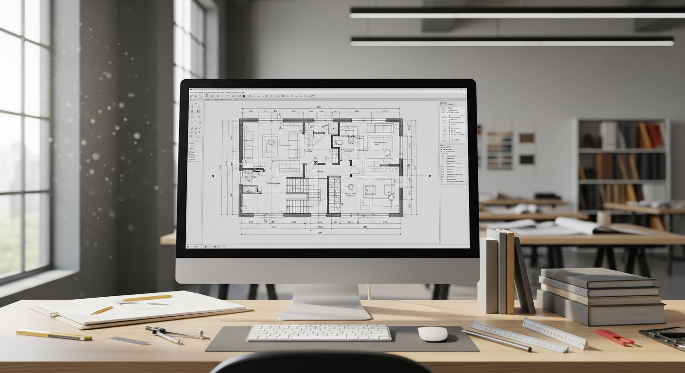
A floor plan is only one view. Many misunderstandings happen because readers expect the plan alone to answer questions about height, exterior appearance, ceiling slope, roof form, or vertical clearances. That is where elevations and sections matter.
An elevation is a straight-on view of one side of the building or one interior wall. It helps you understand window placement, door height, grade relationship, and exterior composition. If you want a simple introduction, see what an elevation drawing is. A section, by contrast, slices vertically through the building so you can see floor-to-ceiling relationships, roof lines, and stacked construction elements.
When you see a section marker on the plan, do not ignore it. It tells you exactly where the building has been cut for another drawing. That view may answer questions the plan cannot, such as:
- How tall is the ceiling in this room?
- Is this step down one riser or several?
- Does the roof slope over this area?
- Is this wall full height or partial height?
- How does the building meet the grade outside?
Good readers move back and forth between sheets. They do not treat each page as separate. They use references to build a mental 3D understanding of the building from multiple 2D views.
Watch for real-world irregularities in existing California buildings
As-built drawings document reality, and reality is often messy. Older California homes and commercial spaces commonly include non-square rooms, additions from different eras, shifted wall lines, sloped floors, or field modifications that do not match old permit records. Reading an as-built set well means expecting some imperfection.
This matters especially in California renovation work because local permitting often depends on accurately representing existing conditions before any proposed changes are reviewed. That can affect ADUs, SB 9 lot split projects, tenant improvements, and code-triggered upgrades. Building departments may also ask for clarification when older structures have undocumented modifications. Requirements can vary by city and county, so you should always confirm details with the local jurisdiction.
For historic properties or older multifamily buildings, related compliance issues may also shape what information is needed. Depending on the project, owners may need to think about matters such as Title 24 energy compliance, balcony inspection laws like SB 721 or SB 326, or local historic review under programs such as the Mills Act. The drawings themselves do not replace code analysis, but they provide the reliable existing-condition base that consultants and permit reviewers use to make those decisions.
If you are trying to understand why this record matters so much before design starts, it helps to read more about why as-built drawings matter for every project. Accurate measured plans reduce avoidable surprises later.
Compare as-built drawings with other document types carefully
Another big part of learning how to read as-built drawings is knowing what they are not. People often confuse them with blueprints, record drawings, site plans, and measured drawings. Those terms overlap in conversation, but they can point to different scopes and uses.
- Blueprints: A common informal term for plans, but not a precise description of existing measured conditions.
- Design drawings: Show proposed work, not necessarily the current layout.
- Record drawings: May reflect project changes recorded during construction, depending on how they were maintained.
- Measured drawings: Can overlap strongly with as-built work, especially when created from field measurement of existing conditions.
- Site plans: Focus more on the parcel, setbacks, access, and building placement on the lot.
If you want to sort out these distinctions in more detail, useful comparisons include as-built vs. record drawings and whether as-built and measured drawings are the same. Reading the right kind of document the right way saves time and prevents bad assumptions.
How FastAsBuilt organizes deliverables so they are easier to read
Clear drafting standards make a plan set more usable. FastAsBuilt provides field-measured as-built drawings and measured floor plans across California, with local crews serving Southern California, the Bay Area, and San Diego. The process starts with on-site laser measurement. Senior drafters then produce permit-ready CAD files delivered in PDF and DWG format.
For many residential projects, 2D As-Built Plans start at $900 for up to 1,500 square feet, then $0.50 per square foot, include one revision, and are typically delivered in 48 to 72 hours. For projects that need a fuller spatial record, 3D As-Built Plans start at $1,500, then $1.00 per square foot, and include a 3D model plus 2D floor plans, elevations, and sections, with two revisions and typical delivery in 3 to 5 business days. Commercial work, ADUs, SB 9 projects, and tenant improvements are quoted individually.
Turnaround times are estimates and may vary based on project complexity and scheduling.
If you are reviewing a plan set for a remodel or permit package, organized sheet titles, consistent symbol use, and accurate field dimensions make a major difference. If you need a current measured set, you can review options on our packages page before ordering.
Frequently asked questions
What is the first thing to check when reading an as-built drawing?
Start with the title block and sheet title. Confirm the address, sheet type, date, revision status, and scale. Then identify whether you are looking at a floor plan, elevation, section, or detail. That context changes how every symbol and line should be read.
Can you scale measurements directly from a PDF?
You can use scale for approximate understanding, but written dimensions should always control. PDF viewing, printing, and page reduction can distort physical measuring. If a dimension is critical for design, fabrication, or permit work, rely on the noted measurement and confirm field conditions when needed.
Do all as-built drawings include electrical, plumbing, and structural information?
No. The content depends on the project scope. Some as-built sets focus on architectural layout only, while others include selected building systems. Always check the sheet index, notes, and legends to see what is included. If systems are important to your project, confirm that scope before the work begins.
Why do as-built drawings sometimes differ from old permit plans?
Because buildings change. Previous owners may have altered walls, added fixtures, enclosed spaces, or modified layouts over time. Older permit files can also be incomplete. As-built drawings are valuable because they document current observed conditions rather than relying only on historical paper records.
Are as-built drawings enough for a permit application?
Usually they are the starting point, not the full permit package. Jurisdictions generally need proposed design drawings and may require structural, energy, accessibility, or site-specific information depending on the project. In California, permit expectations vary by city and county, so confirm requirements with the local building department.
Start with accurate as-builts
Order field-measured 2D or 3D as-built drawings and let a local crew handle the measuring and drafting.
Get instant pricingBottom line
Learning how to read as-built drawings comes down to a repeatable process: start with the title block, check the scale, understand the line types, identify common floor plan symbols, read dimensions from overall to specific, and follow notes and callouts across sheets. Once you do that, the drawings stop feeling abstract and start working as a practical tool. And if you need a reliable set to begin with, FastAsBuilt provides field-measured, permit-ready as-built drawings throughout California.