
If you are asking what is a detail drawing, the short answer is simple: it is a close-up drawing that explains exactly how one specific part of a building should be built, connected, or documented. While a floor plan shows the overall layout of rooms and walls, a detail drawing zooms in on a small area—such as a stair edge, window jamb, parapet, roof-to-wall connection, cabinet section, or foundation condition—so the dimensions, layers, materials, and joinery are clear.
Detail drawings matter because many construction problems happen where parts of a building meet. A contractor may understand the general plan, but still need a larger-scale view to see fastening, clearances, waterproofing, finishes, or structural relationships. For owners, architects, engineers, and contractors across California, detail drawings help turn broad design intent into something buildable and reviewable. They also become especially useful when paired with accurate field-measured existing conditions, such as as-built drawings and measured floor plans prepared from on-site laser measurement.
What a detail drawing means in practical terms
A detail drawing is a scaled drawing that focuses on one assembly or condition instead of the entire building. It usually appears at a larger scale than the main plan, elevation, or section so the information can be read clearly. In practical use, that means it answers questions the main drawing cannot answer on its own.
For example, a floor plan might show where a window sits in a wall, but a detail drawing can show:
- The wall thickness and material layers
- How the window frame is set into the opening
- Flashing, sealant, and waterproofing locations
- Trim dimensions and finish transitions
- Attachment points and tolerances
That level of clarity reduces guesswork. It also helps design teams communicate with plan reviewers, fabricators, and installers. In remodels and additions, detail drawings often rely on measured existing conditions, especially when older California buildings do not match prior permit sets.
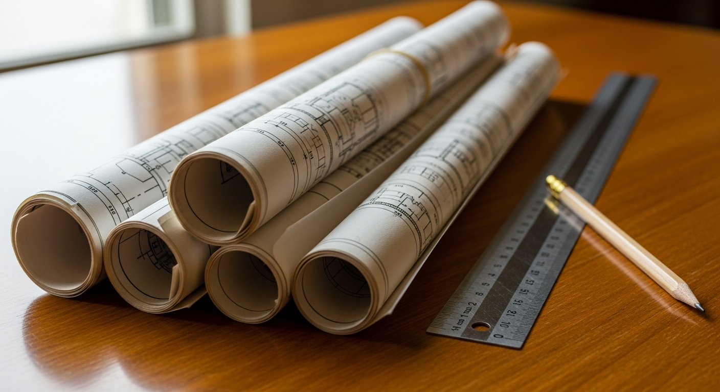
What information is usually shown on a detail drawing
Not every detail drawing looks the same, but most include a consistent set of information. The purpose is to make one condition easy to understand without forcing the reader to interpret too much from surrounding sheets.
- Scale: Usually larger than a floor plan, such as 1 1/2" = 1'-0", 3" = 1'-0", or similar enlarged views
- Dimensions: Precise distances, thicknesses, heights, offsets, and clearances
- Material callouts: Notes that identify wood, concrete, metal, gypsum board, insulation, tile, roofing, waterproofing, and finish materials
- Connection notes: Fasteners, anchors, welds, clips, brackets, adhesives, or attachment methods
- Section cuts and references: Tags pointing back to plans, elevations, or building sections
- Keynotes or general notes: Written instructions for construction intent
Some details are architectural, some are structural, and some are interior or millwork-related. Others focus on accessibility clearances, waterproofing transitions, or energy-related assemblies that may affect Title 24 compliance. In California, project requirements vary by city and county, so the exact level of detail should always be confirmed with the local jurisdiction and the project design team.
Why detail drawings are important on real projects
On real jobs, detail drawings are less about theory and more about avoiding expensive confusion. If the plans only show a broad layout, people in the field may interpret the same condition in different ways. That can lead to rework, delays, water intrusion, coordination problems, or permit comments.
Detail drawings are especially important when:
- An existing building has unusual conditions that need to be documented accurately
- Several trades must coordinate in a tight location
- Moisture control, fire separation, or accessibility matters
- A remodel ties new construction into older framing or finishes
- The permit reviewer needs clearer documentation of how something will be built
For existing buildings, measured drawings can reveal field conditions that affect detailing. That is one reason many owners first gather what is included in as-built drawings before starting design. Accurate base information leads to better details, and better details usually lead to fewer surprises during construction.
Need accurate as-built plans?
FastAsBuilt sends a local crew to laser-measure your property and delivers permit-ready 2D or 3D drawings, starting at $900.
See 2D & 3D pricingDetail drawing vs floor plan
One of the most common comparisons is detail drawing vs floor plan. They are related, but they do very different jobs.
A floor plan is a horizontal cut through the building, usually showing walls, doors, rooms, circulation, fixtures, and overall dimensions. It helps you understand layout and spatial relationships. If you need a refresher, see what an as-built floor plan is.
A detail drawing, by contrast, isolates one small condition and magnifies it. It is not mainly about layout. It is about construction logic.
Key differences
- Purpose: Floor plans show where things are; detail drawings show how specific parts go together
- Scale: Floor plans are broader; details are enlarged for clarity
- Content: Floor plans show rooms and walls; details show materials, joints, edges, and connections
- Use in the field: Floor plans guide placement; details guide assembly and finishing
Think of it this way: a floor plan might tell you a restroom door is 3 feet wide and located on the west wall. A detail drawing might tell you the exact jamb condition, backing, frame type, threshold, finish transition, and required clearances at that opening.
Most permit sets use both. Plans, elevations, and sections establish the overall design, while details resolve the difficult moments. That same relationship exists between details and other drawing types, including elevation drawings and sections.

Common types of detail drawings
Detail drawings appear across many disciplines. The exact mix depends on the project scope, the existing building, and what the local reviewer wants to see.
Architectural details
- Wall sections at windows and doors
- Roof edge and parapet details
- Interior finish transitions
- Stair, guardrail, and handrail details
- Restroom accessibility details
Structural details
- Footing and rebar conditions
- Post bases and anchor bolts
- Beam connections
- Shear wall nailing or holdown conditions
- Framing tie-ins at remodel areas
Interior and millwork details
- Cabinet sections
- Counter edge profiles
- Reception desk assemblies
- Built-in shelving and banquette details
MEP-related enlarged details
Mechanical, electrical, and plumbing sheets may also include enlarged views or installation details where equipment clearances, penetrations, supports, or coordination need to be shown. Depending on the scope, owners often ask whether as-built drawings include electrical and plumbing before deciding how much existing information to capture.
Detail drawing example
A useful detail drawing example is a typical exterior window sill detail in a stucco wall. On the floor plan, you may only see the window location and rough size. On the elevation, you may see the exterior appearance. But neither one fully explains how the bottom of the window handles water and connects to surrounding materials.
A detail for that condition might show:
- The stud wall and sheathing behind the finish
- Weather-resistive barrier and flashing layers
- The window frame profile and sill slope
- Sealant joints and backing
- Stucco termination or trim condition
- Dimensioned offsets between face of frame and exterior finish
This is exactly the kind of issue where enlarged documentation matters. If one flashing leg is omitted or a finish line is unclear, water can get behind the wall. The detail makes the invisible logic visible.
Another example is a stair detail. A plan can show the stair run and width, but a detail can clarify tread profile, riser dimensions, handrail returns, guard attachment, finish nosing, and any transitions at top and bottom landings. In tenant improvements, ADUs, and single-family remodels, these small clarifications often make permit review and field execution much smoother.
How detail drawings relate to as-built drawings
Detail drawings are often associated with new construction documents, but they also matter in existing buildings. When a project starts with old, incomplete, or unreliable plans, a designer may need fresh as-built documentation before creating details that tie into the structure accurately.
For example, if you are renovating an older Los Angeles duplex, expanding an ADU in San Diego, or planning a tenant improvement in the Bay Area, the existing wall thicknesses, framing depths, floor level changes, and opening conditions may differ from prior drawings. If those base dimensions are wrong, any details built from them may also be wrong.
That is why FastAsBuilt begins with on-site laser measurement and then senior drafters produce permit-ready CAD files in PDF and DWG format. For many California projects, that measured baseline becomes the foundation for later detailing by the architect or engineer. If you are comparing documentation types, it also helps to review as-built vs design drawings so you can separate existing conditions from proposed work.
FastAsBuilt provides field-measured 2D as-built plans starting at $900 for up to 1,500 square feet, then $0.50 per square foot, with one revision and typical 48–72 hour delivery. 3D as-built plans start at $1,500, then $1.00 per square foot, and include a 3D model plus 2D floor plans, elevations, and sections, with two revisions and typical delivery in 3–5 business days. Commercial properties, ADUs, SB 9 projects, and tenant improvements are quoted individually. If you already know your scope, you can start at our order page.
Turnaround times are estimates and may vary based on project complexity and scheduling.
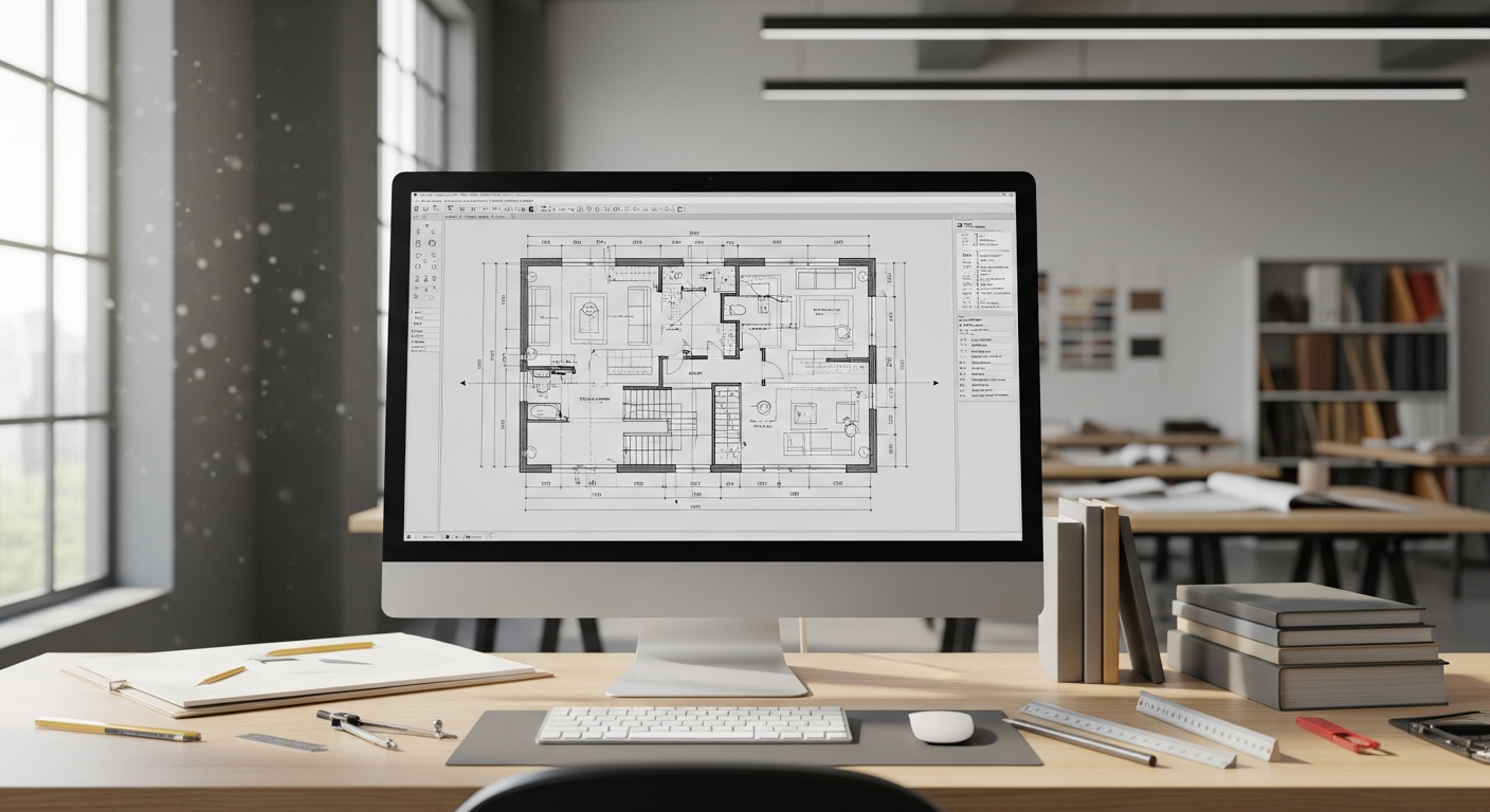
When you need a detail drawing
You do not need a detail drawing for every simple sketch, but you usually need one when a condition cannot be understood from the main drawing set alone. The more complex, regulated, or coordination-heavy the condition, the more likely a detail is necessary.
You may need detail drawings when:
- You are preparing permit documents for a remodel, addition, ADU, or tenant improvement
- You are tying new work into an existing building with uncertain dimensions
- You need to clarify waterproofing, accessibility, fire separation, or structural connections
- You are documenting custom millwork or built-ins for fabrication
- You are responding to plan-check comments asking for enlarged views or sections
California projects often involve additional layers of review depending on the property type, age, and scope. Issues related to accessibility, energy performance, multifamily conditions, or exterior elevated elements may lead consultants or jurisdictions to request clearer documentation. Rules tied to matters such as Title 24, SB 721, SB 326, SB 9, AB 1033, AB 2533, SB 1211, or local historic programs like the Mills Act can affect project decisions at a general level, but the exact application depends on the property and local jurisdiction. Those requirements should always be confirmed with the city or county reviewing the permit.
How detail drawings are created
The process usually starts with a base drawing. That may be an architectural plan, an elevation, a building section, or an as-built survey of existing conditions. The design team identifies locations that need more explanation and creates enlarged references to those spots.
A typical workflow looks like this:
- Measure or verify existing conditions in the field if the project involves an existing building
- Create base plans, elevations, and sections
- Mark critical locations needing enlarged documentation
- Draft detail views at a larger scale
- Add dimensions, notes, material layers, and connection information
- Cross-reference the detail back to the main sheet set
On remodel projects, field verification matters. A detail may seem minor on paper, but if an existing slab steps down, a wall is thicker than expected, or an old window opening was altered over time, that can change the detail significantly. That is one reason measured documentation is often the first practical step before design work begins. If you are still learning the basics, our article on how to read as-built drawings, symbols, scales, and conventions can help make these sheets easier to understand.
What detail drawings do not replace
Detail drawings are important, but they are not a substitute for the rest of the drawing set. They work as part of a system. You still need plans to understand layout, elevations to understand appearance, and sections to understand vertical relationships through the building.
A detail drawing usually does not replace:
- Floor plans: for room arrangement and overall dimensions
- Elevations: for exterior or interior faces and heights
- Sections: for broader cut-through relationships
- Schedules: for doors, windows, and finish information
- Specifications: for product standards and installation requirements
It also does not automatically prove field accuracy. A beautifully drafted detail can still be based on bad assumptions if the existing building was never measured correctly. For that reason, many teams first establish dependable existing drawings before advancing to permit detailing and consultant coordination.
Frequently asked questions
Is a detail drawing the same as a floor plan?
No. A floor plan shows the overall arrangement of spaces and building elements from a horizontal cut. A detail drawing enlarges one small condition to show exactly how it is assembled, dimensioned, and connected.
What scale is a detail drawing usually drawn at?
There is no single required scale, but detail drawings are usually drawn larger than the main plans so construction information is legible. The chosen scale depends on how much information must be shown clearly.
Who uses detail drawings?
Architects, engineers, contractors, fabricators, permit reviewers, and property owners all use them. Each group relies on details for a different reason, but the shared goal is clearer communication and fewer assumptions in the field.
Are detail drawings used for existing buildings?
Yes. They are often used when renovation or addition work must tie into existing construction. In those cases, measured as-built drawings help establish the real-world conditions that the detail needs to address.
Do detail drawings need to be permit-ready?
That depends on the project stage. Early concept details may be informal, while permit sets usually need clearer dimensions, notes, and coordination with the rest of the drawings. Local review expectations vary across California, so confirm requirements with the jurisdiction handling your project.
Start with accurate as-builts
Order field-measured 2D or 3D as-built drawings and let a local crew handle the measuring and drafting.
Get instant pricingBottom line
A detail drawing is a close-up construction drawing that explains how a specific building condition is put together. It does not replace a floor plan, but it adds the precision that general drawings often cannot provide. If you are planning work on an existing California property, accurate measured drawings are the best starting point for dependable detail development—and FastAsBuilt can help provide that foundation with field-measured, permit-ready as-built plans.